This page is dedicated to the construction and buildup of my scratchbuilt 1/32 scale Nautilus from Disney's 1954 classic, "20,000 Leagues Under the Sea".
This project was started in November of 2001, and took nearly three years to complete.
Much of the time was taken in trial and error, as this was my first venture into the world of RC and also my first scratch-built model. This model brought me into the world of R/C submarines, and I've been hooked ever since.
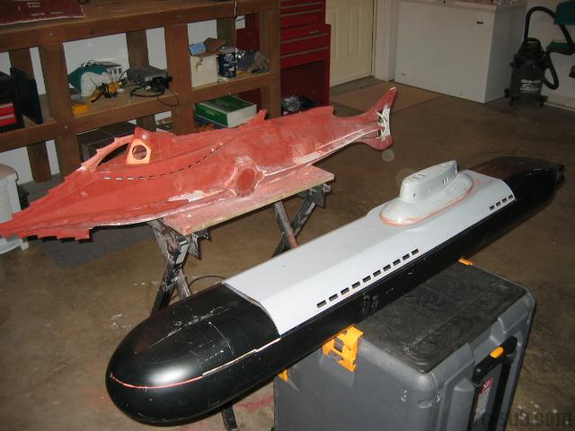
This model was created from blueprints done by Tor Jensen, and supplied by Vikki Ford in the UK on her website (now defunct). The completed model is 1:32 scale, measuring approximately 66-1/2" from ram tip to tail.
The dates in this posting will be somewhat muddled, as it was done prior to me dating my work. The order is correct, however.
January 23, 2001
My dreams of owning a Nautilus resulted in the creation of this model. The master took a total of one year to complete, working an average of a half an hour per day. I'm sure that I could do it much faster if I were to do it again (which I'm hoping to), with the aid of computerized cutting of the framework templates. A skin of brass or aluminum would be my next preference, and my next Nautilus will be made from water-friendly materials so as to eliminate the need for molds.
I was originally inspired to attempt this model when I found Vikki Ford's website chronicling her own attempts at modeling this challenging subject. Her own project ended in a less than satisfying way when her fiberglass molds fused to her fiberglass casting. Unfortunately, in the process of molding her model, her master was destroyed. Learning from (some) of her mistakes, I utilized Tor Jensen's blueprints (posted on Vikki's site) to begin the construction of my own Remote Controlled Nautilus.
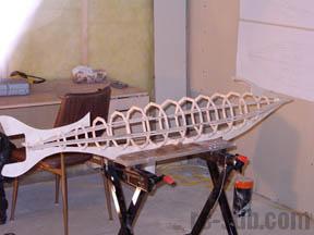
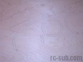
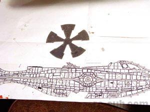
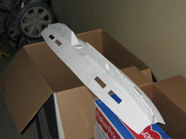
I used birch plywood as the material only because it was on sale, and was easily sanded and finished. The first step was to print the blueprints in 1:1 scale. I asked a friend who works at an oilfield supply company to plot the blueprints on his plotter. That done, I transferred the templates to my 1/4" birch plywood to cut out the framework of the Nautilus. The ribs, keels and rakers were then cut out using a jigsaw. A scroll saw would be a far better tool for the job, but as I didn't have one, I made do.
Once the parts were cut out, they were sanded of all rough edges. That done, I test fit all of the parts for alignment. This step went very well, and was probably the most rewarding step of the model to date, taking a collection of two dimensional pieces, and making them into a three dimensional model in the course of a few minutes. Very satisfying.
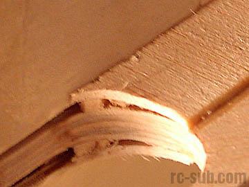
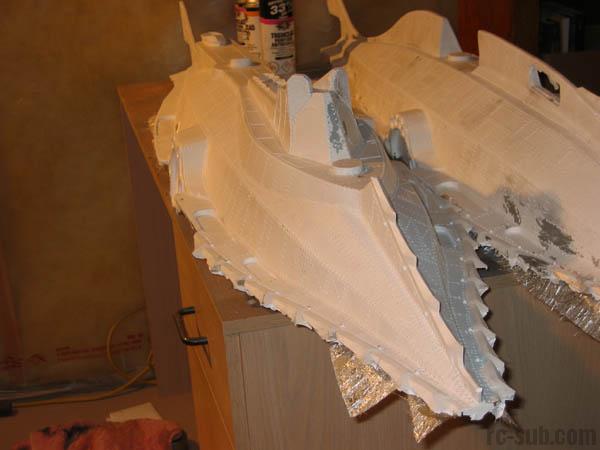
Once the alignment was ensured, I began gluing the parts using thick CA glue. By utilizing a series of clamps and bars, I was able to ensure that the side keels, main keel, upper raker, and tail were exactly in line. The main framework completed, I then turned my attention to "skinning" the hull. I would like to say that I used a series of highly complex mathematical calculations to do so perfectly, but the truth is that I was pretty good at "winging it" and used a lot of trial and error to get the shape right. My hull plating runs from tail to nose, ten pieces in all. I did this primarily for strength, as at the time I was intending this wooden hull to be laminated in resin for watertightness. An added bonus is that the hull is smooth and streamlined. If I were to it all again, I would have utilized 1/16" modeling plywood for the hull plating, as the 1/8" birch that I did use was extremely tough and resisted curving.
With the hull plated, I began work on the main deck. I traced the deck from my blueprints and then transferred it to my 1/8" birch plywood. I then cut it out using a jigsaw. A duplicate deck that was inset exactly 1/8" from all edges was created and glued to the bottom of this deck to help with skirting later. I set up spacers on the superstructure to ensure proper alignment, and then glued the deck in place.

January 24, 2001
I then decided to tackle the wheelhouse. This was fairly straightforward, with no unforeseen difficulties arising. The next (very tedious) step was to add the deck skirting. I chose to use a series of plywood strips, approximately 3/4" wide to do so. I wasn't too worried about looks at this point, as I knew that I was going to use filler to smooth things over later. This is where the 1/8" inset helped out. The pieced fit snugly into the upper deck lip and were glued directly to the hull at the bottoms.
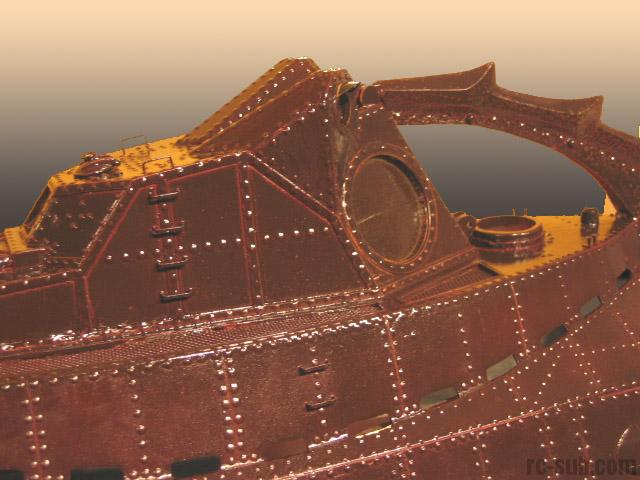
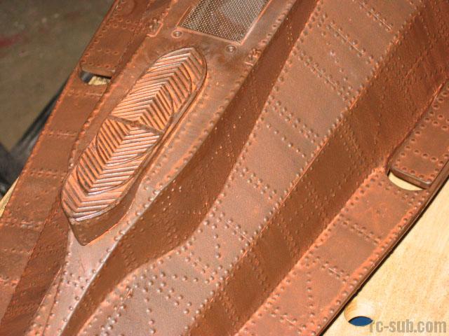
Next step were the so called "alligator eyes". My blueprints called for larger structures meeting in the center. A smaller model of mine showed them more streamlined with a space in the middle. I took some artistic license and decided to go with the more streamlined eyes. I have since taken some flak from Nautilus purists, but comparing the eyes side by side, I have to say that I like the way that I modeled it better than the larger ones. Also tackled at this point were the breather flaps behind the wheelhouse. They were made from 1/8" plywood cut to shape.

January 25, 2001
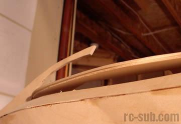
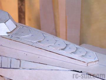
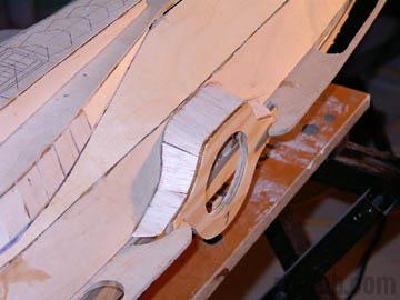
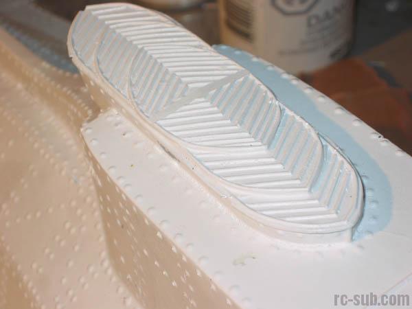
The salon windows were my next project. I cut out the facing from 1/4" birch, aligned them properly with spacers, and then glued them in place. I then decided to try 1/16" balsa to form the curved shrouds rather than the series of small pieces like what I did with the deck skirting. I worked extremely well, with my only complaint being the strength of the material. I then cut the pieces to represent the breather panels behind the wheelhouse. Each piece's trailing edge sat on the piece behind it, creating the stepped structure.
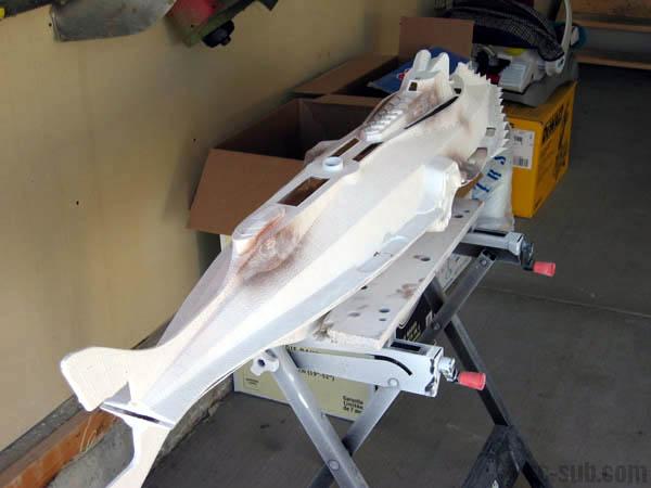
The next step involved fattening my rakers. I laid 1/8" thick strips of balsa against the hull on the rakers along the entire length, and then added a 1/16" balsa layer on top of that. I probably didn't need to do so, as bondo or wood filler would have done a fine job, but it made for a nice intermediate step, even if I could have safely skipped it. This was done to the side rakers, keel, upper rakers, and tail fins.
Filling and sanding followed. This step turned the rough Nautilus hull into a sleek vessel. I found that bondo works by far the best of all of the product I tried. Wood filler actually softened up with prolonged sanding with a mouse sander, causing gummy holes to appear after a few seconds. Bondo seems to have been designed for this application, and works far better. I hindsight, I'd have been a lot more careful in the application of my CA glue that I used to glue my hull together, as CA does not sand well.
January 26, 2001
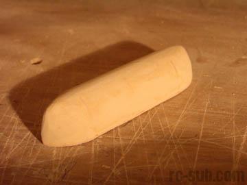
I decided I needed a little break from the main boat and took on the skiff. I built the ribs from 1/16" balsa and then simply filled in all of the gaps with good wood filer. A crude, but effective solution. The skiff actually turned out very well.
October 27, 2001
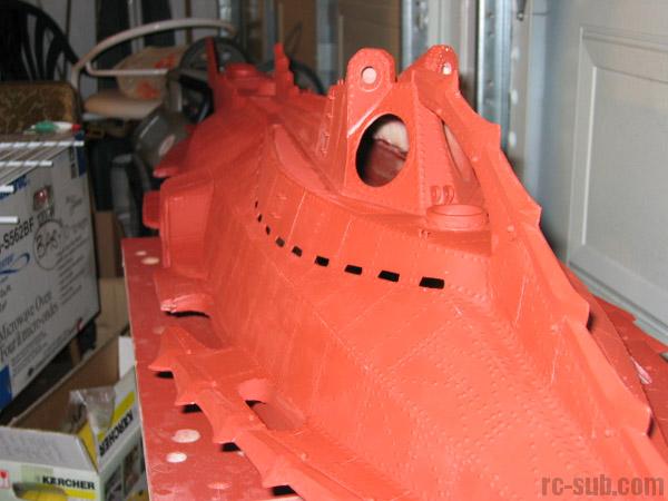
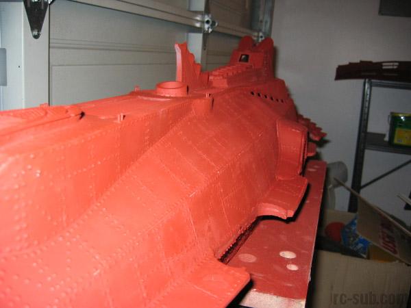
After all of the sanding and filling was complete, I primed the model with red oxide primer. This layer of paint showed all of the minor imperfections nicely, and allowed me to fill and re-sand any hiding problem areas.
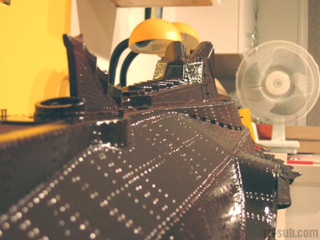
After the primer came over four cans worth of high gloss black spray paint. By the time I was done, you could literally see your reflection in the hull surface. The reason that I went with gloss paint was so that the rivets in the next step would bead nicely and sit up as high as possible. Flat finish paint simply absorbs the glue and spreads the rivet over a 1/4" area. Not good at all.
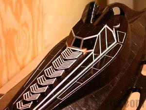
After the painting was completed, I began the task of scribing the hull for panel lines. William Babington generously supplied the blueprints for this step, which included all of the panel lines and rivet patterns. A sharp utility knife was used for this task, used reversed to make a sharp, but visible furrow. The knife was very hard to control in places, and if you have access to a scribing tool, by all means utilize it.
All of the smaller details were then added using strip styrene. The reinforcement bezels and grating outlines were all added using half round and flat styrene strips and thin CA glue. The skiff top and breather flaps were the most time-consuming (particularly the skiff top). Each strip was added individually by hand. Next time I think I'll spring for a computer laser cutter to get the job done.

October 28, 2001
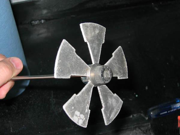
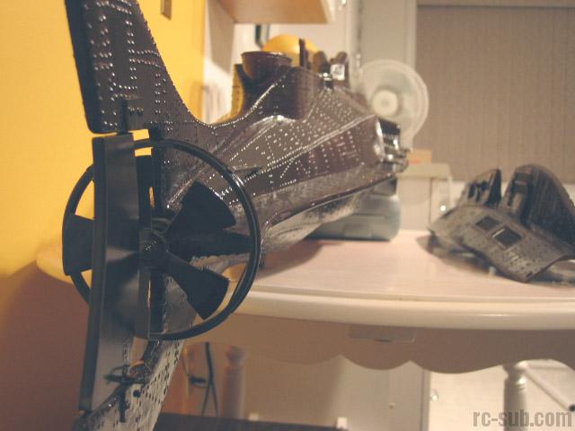
At this time, I concentrated on my propeller. I took Will's propeller drawings and redid them in CorelDraw. I then got my brother-in-law to cut the entire prop silhouette using his CNC cutting table. I used 1/16" thick aluminum plating for this, as I liked the light weight, and the thin material. I really wanted to go with the classic "sledgehammer" design of the original over a more modern four or five-bladed prop. My research has determined that the overall performance will suffer, but not by too great a degree.
October 29, 2001
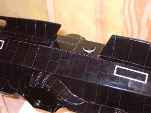
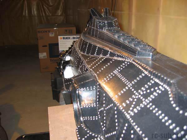
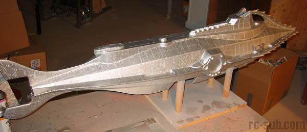
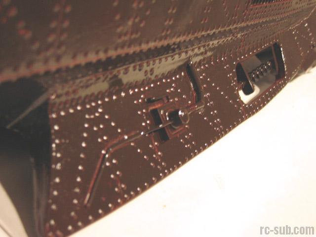
Next came the monumental task of riveting the entire hull. There are well over 20,000 rivets, and each one was individually applied using a thick solution of epoxy and thickener and a soldering application tool. This process took about two months of working about and hour a day. As the job progressed, I became faster and faster, and the rivets became more uniform and better shaped. This was lots of work, but is absolutely necessary for the full Nautilus effect (in my opinion).

October 30, 2001
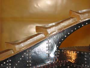
My next project was to fashion the raker teeth master and the dorsal fin. I used the birch plywood for this, as it is a fairly hard wood, yet is easy to shape and sand.
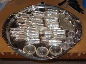
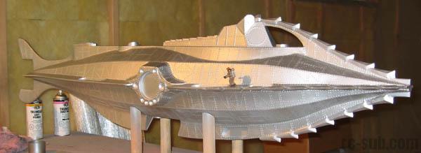
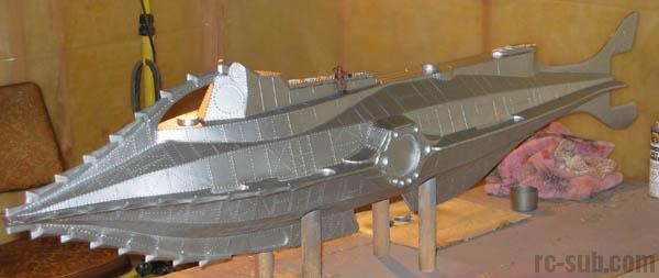
That done, I created molds using a sample kit of Smooth-On's PMC30 rubber. There was more than enough to create the molds. The teeth were cast in clear casting resin. This process went very well and I averaged five teeth castings per day. The Nautilus takes 32 teeth in all (my dorsal fin was created in one piece, including the teeth there). The teeth were then secured to the hull using JB Quick Weld (I absolutely love this stuff).
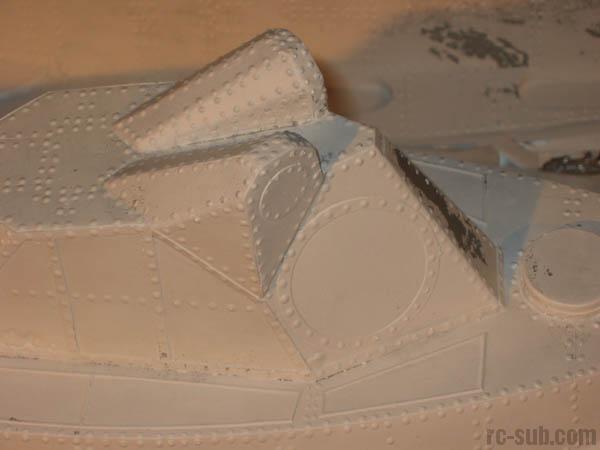
The rivets along the base of the teeth were then added, and the large retaining bolts for the teeth were added using small "google" eyes, which I will also use for the lenses on my floodlights. The entire model was then primed with automotive primer to seal the hull. This is when all of my hard work really solidified. The rivets accented the hull perfectly, not too large to overwhelm the model and not too small to fade away when you look at it.

October 31, 2001
At this point I needed to create a mold from which I could create a fiberglass casting.
The first step involved deciding where to split the model for lay-up. After consulting with my fiberglass artist, we decided to split the model along the center of the sidekeels. This would provide the best arrangement for laying up the fiberglass matting during lay-up.
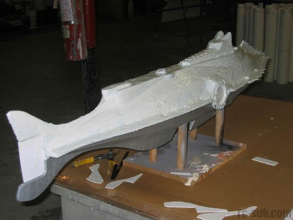
That done, we began by coating the model with mold release. I used Ease Release 200 for this purpose. Two coats are applied. The first is applied with the spray can and then spread over the model with a soft bristled brush. The second is another light coat with the spray can only.
The rubber is then mixed up. I used Smooth-On's Brush-On 40 for this purpose. The two parts are mixed 1 to 1 and form a mixture that is the consistency of cake frosting. After complete mixing is assured, the first coat of rubber is applied using a brush. This first coat is very thin to ensure that no air bubbles are trapped against the hull.
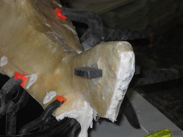
The first coat of rubber took about 90 minutes to tack up properly. The second batch of rubber was then mixed up and applied in a nice, thick layer using a combination of a large brush and a rubber spatula. We took extra care to fill the areas that has undercuts and hard angles. The idea was to end up with a surface that is as featureless as possible.
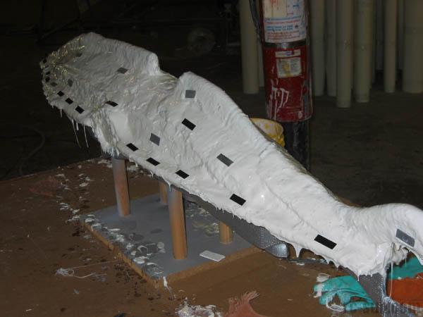
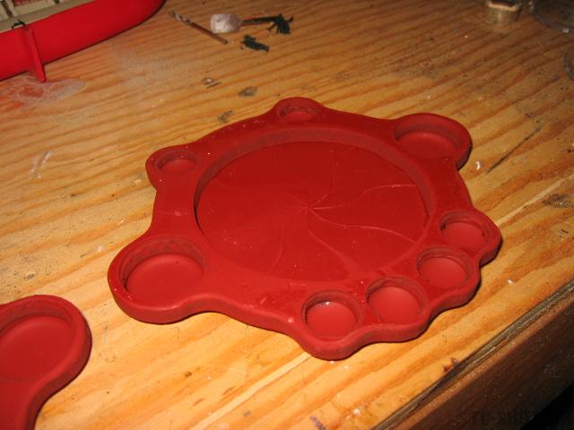
The next layer was composed of strips of old rags saturated in rubber, applied when the second layer tacked up. These strips were applied over the entire model to add rigidity and volume to the mold. Once all of the strips were applied, another generous layer of rubber was applied to the entire surface. The final product should have a minimum of 3/8" to ½" of rubber over the entire model, with significantly more in undercut areas. We also decided to try something different to keep the rubber tight against the shell in the next stage. We embedded small pieces of metal in the rubber. After the fiberglass shell is applied, we should be able to use magnets to hold the mold tight against the shell, ensuring a properly aligned lay up.
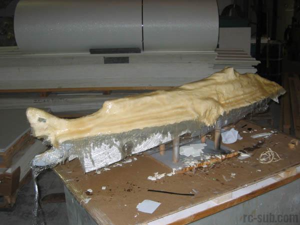
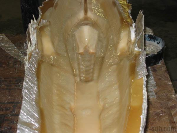
The next step involved applying that fiberglass shell over the entire model. This formed a support for the rubber and ensured that the mold was properly aligned for casting or lay-up. The rubber surface was coated with mold-release and then the resin and heavy glass matting was applied in a single strong layer. We made sure that the tail section would release when it came time to remove the shell.
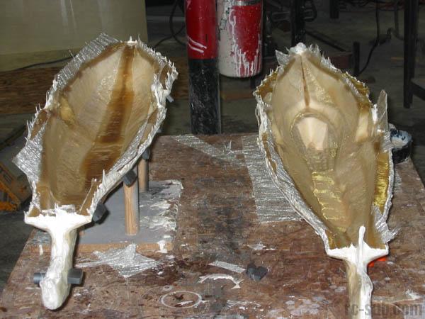
When the layer of fiberglass was properly cured, this layer was removed from the model, followed by the rubber, which was peeled off of the master carefully from bow to stern. When the rubber is placed back into the fiberglass shell and the shell properly braced, we had our upper mold. . The magnets that we had embedded seemed to work very well to keep the rubber tight against the fiberglass, and the indentations that they made in the shell acted like a keying system of sorts.
The same procedure was followed for the lower half of the model as we did for the upper half.


October 23, 2002
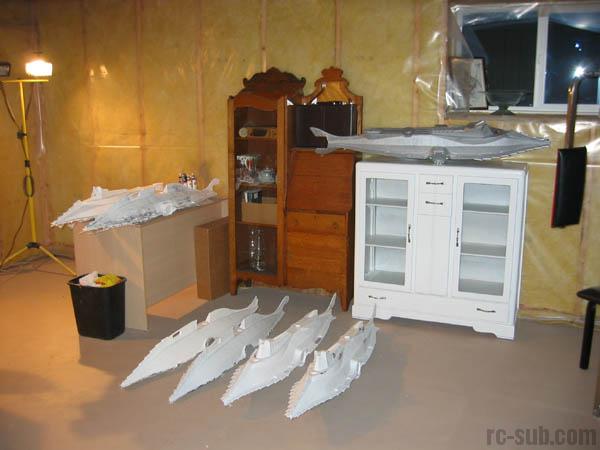
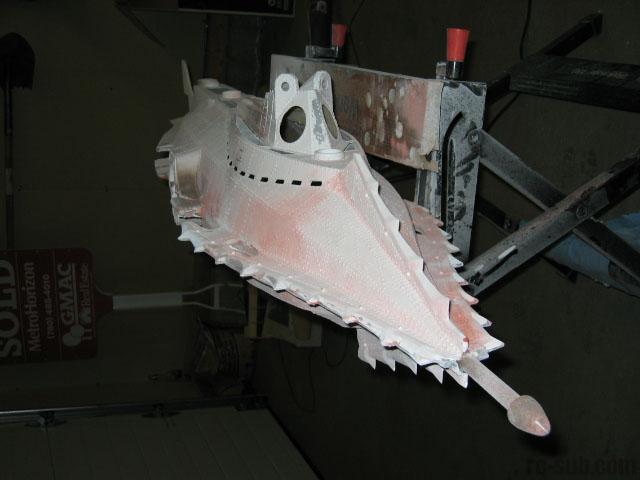
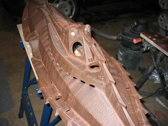
The layup of this model is very tricky, and I contracted with George Reid from Ideal Plastics in Edmonton to do all of my layups. The myriad of sharp angles make getting all of the air out of the corners a real challenge, and a few always seem to pop up under the layer of gelcoat. An unforeseen benefit of this is an authentic looking "worn" effect. The gelcoat ripples slightly at these points, and look like dents and dings that the Nautilus might have suffered throughout her career of ship-bashing.
The castings are done up in polyester resin and fiberglass. A layer of white gelcoat ensures a smooth finish on the exterior. Side rakers and the keel are casting resin mixed with fiberglass chop. This provides an extremely hard and durable finish on the pieces of the model that are the most subjected to bangs and crashes. The upper half is laid up quite thin to cut down on weight and in turn reduce the necessary size of my ballast tank. I estimate the weight of the castings to be approximately 5lbs.
The castings are split at the center-line of the side rakers. A grinder is necessary to remove excess casting resin before the two halves can be joined. Access to the interior of my model will be cut into the bottom half of the hull, just along the bottom third of the model.

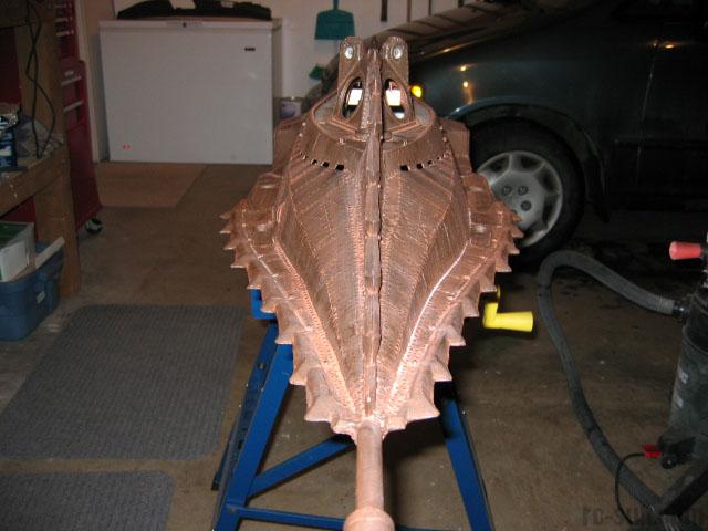
October 24, 2002
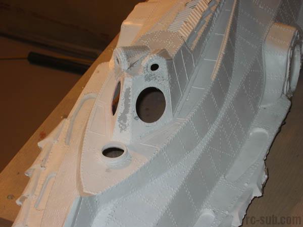
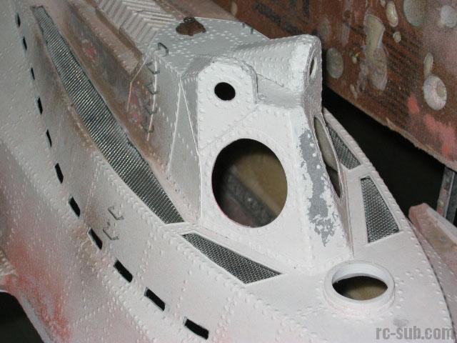
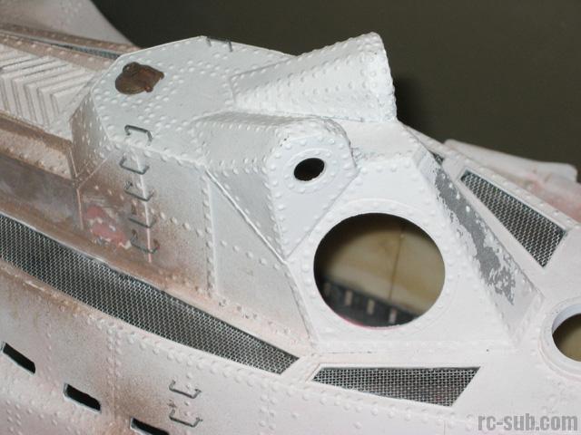
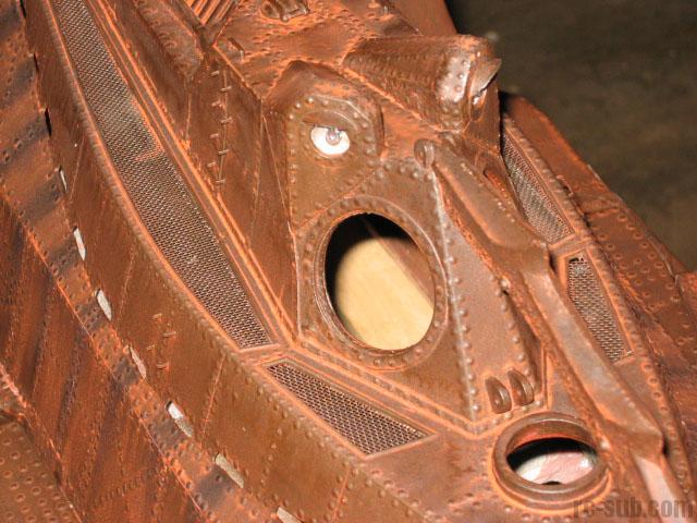
The wheelhouse window was drilled out with a 1-3/4" hole saw and cleaned up with my Dremel. The hatch accesses were drilled out in the same manner with a 1" diameter hole saw. I am waiting to install the interior details and lighting until I have finished grinding the two halves and glued them together, as I am afraid that the vibrations may damage the interior parts and lighting.
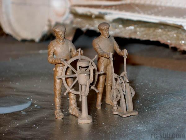
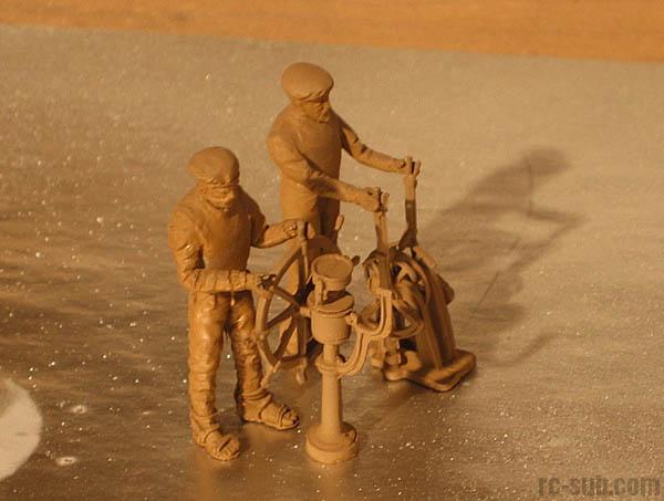
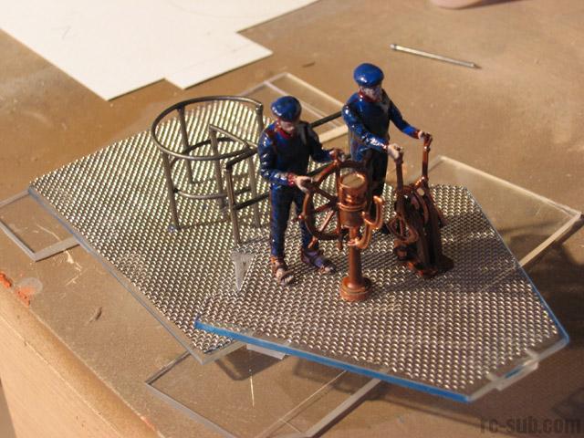
I have also ordered Custom Replica's full interior detail set. This set includes the two authentic Nautilus crewmen, ship's wheel, dive levers, ballast levers, depth gauge, piping, upper bulkheads, and much more. Most of the pieces are cast from white metal, with a few pieces done in resin. After I light the wheelhouse, this interior will add a whole new level of realism to my model.
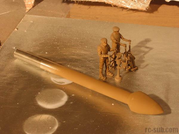
I have also constructed my forward ram. This piece was made from 1/2" stainless steel rod and resin, ground to shape and sanded on my drill press. This tool works well as a makeshift lathe when used with my Dremel or a disc grinder.

October 25, 2002
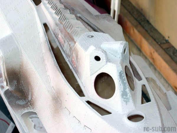
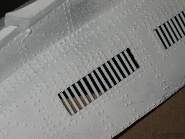
I have cut out the ballast grates and upper decking plates with my Dremel in these pictures. This went very well, and I just need to clean up the edges with a sander and grind a mounting groove into the edges for my stainless steel mesh that I will be using for the decking.
I have successfully glued the upper and lower halves of the hull together using polyester resin and microballoons. I have experienced slight warpage in the sides of the hull, but I don't foresee that being a big problem once I get some reinforcement bulkheads in place. The joint will require some filling and sanding to make it nice and flush, but I'm hoping that the joint will be good and strong.
I have also cut my lower access hatch. This allows for an almost 7" x 36" access opening. This should make the installation of my linkages and internal components a lot easier. I will be mounting aluminum plating on the ends to create a latching system (the details of which will be worked out later.

October 26, 2002
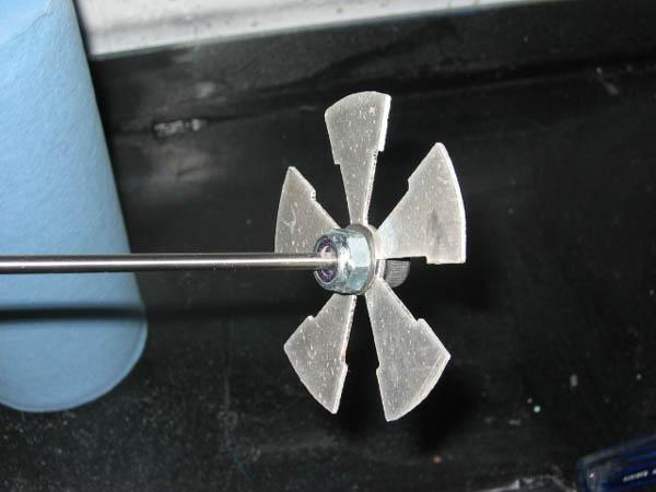
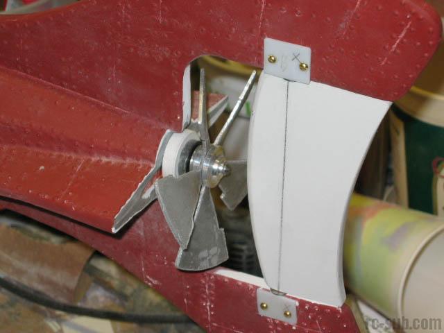
My prop assembly has also been mounted on the drive shaft. I used an allen bolt and lockwasher to sandwich my prop cutout. I am very happy with how it turned out. Once it is mounted, I will do some filling to create the proper look using resin and filler.
Deck grating has been installed. This is made from high-grade stainless steel mesh used in desanders in the oilfield industry. It's available in almost any gauge and weave. I got it for free as scrap from the company that I used to work for. This process was actually a lot harder than it looked. I needed to router in a groove into the underside of the hull to accept the grating. If I didn't, the grating would sit about 1/8" below the deck, and be uneven. Careful work with the router bit on my Dremel took care of it.
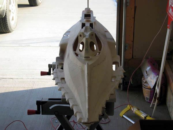
I have also installed my forward ram. This piece was made from a solid piece of 1/2" diameter stainless steel with resin for the bulb. The ram was tacked into place with 5min epoxy and then cemented from the inside with resin. She's not going anywhere soon! This step was necessary, in my opinion, in case the model rams the side of the pool / lake / whatever at full throttle. The ram would need to take quite a shock!
I have begun installing the grating on my ballast intake vents. This is a simple matter of using 1/8" styrene rods and gluing them into place behind the hull. The overall effect is quite good! I'm hoping that these 8 openings will be adequate to quickly flood the hull when submerging.
October 27, 2002
1/2" wide metal strips were installed along the edge of the lower hull access to help maintain rigidity. The rather thin walls allow the hull to warp slightly, and make the hatch not line up well. I'll install some lips to the hatch and hull edges to maintain form.
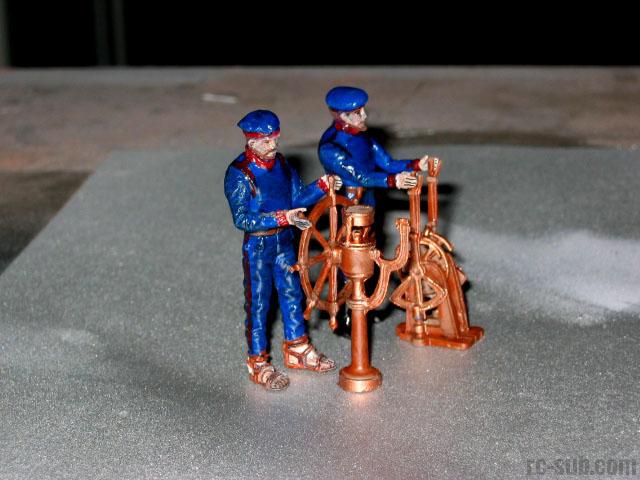
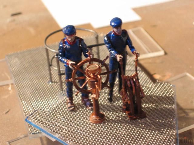
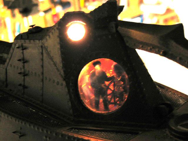
My crewmen have been painted and are now ready for installation. They are a little glossy right now, but they'll be getting a coat of flat lacquer before they are set into the wheelhouse. The lighting in the wheelhouse will be red, so the colors will be a bit more subtle than they look right now.
October 28, 2002
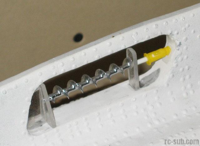
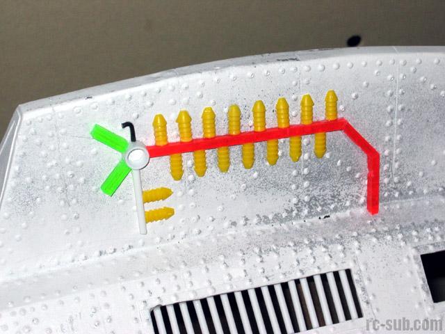
Here are some pics of my newly fabricated lower hull detail pieces. These assemblies are commonly known as the spiral speed indicator, phosphoric atomizer, and gas exchangers. The components are an amalgamation of swizzle sticks, drink straws, drywall anchors, ballpoint pens, and a little bit of Plexiglas. Please pardon the bright colors, and these pieces have not been primed yet, and are their original loud colors. All in all, I'm very pleased with the results.
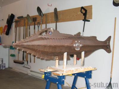
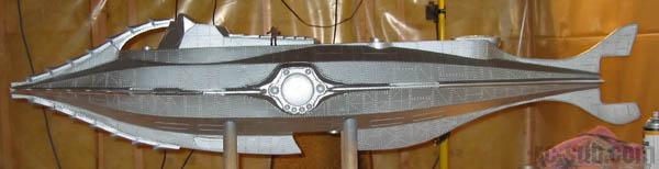
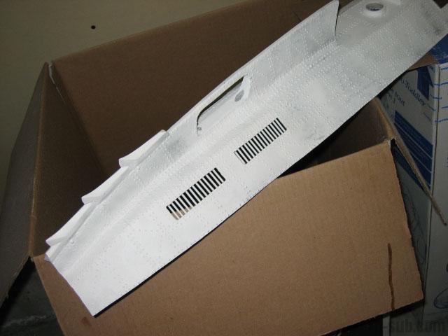
I just had to take some pics of the overall submarine at this point. The vast majority of my sanding is completed in these shots, and she just needs a good washing to get rid of all of the dust. I'll need to prime some spots with gloss paint and redo the rivets, as sanding has removed them back flush with the hull. After 20,000 or so already, what's another few hundred?
The deck is made from 1/8" Plexiglas, laminated with stainless steel mesh. I'm very pleased with the look. Railings were fabricated from finishing nails and wire. The details may not be 100% correct, but they are definitely close enough for anyone looking in through the windows while underway! You will notice that I have decided to center the ship's wheel and the dive levers together in the middle of the wheelhouse. The movie has the wheel in the center of the deck, but I always thought that that was pretty stupid. Firstly, it makes it very squishy for the poor diveplanesman (I'm sure that must be his official name). Secondly, the helmsman can't see a darn thing while he's steering the ship. I've therefore decided to move the wheel to the right so that the helmsman can easily see out the viewport, and give the dive planes more room. My sincere apologies to all of the Nautilus nit-pickers out there.
There is still a bit of detailing and touch ups to do, but the overall effect is quite good. The red oxide primed really finished off the look of the phosphoric atomizer and speed indicators, as indicated in these shots.


October 29, 2002
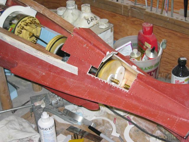
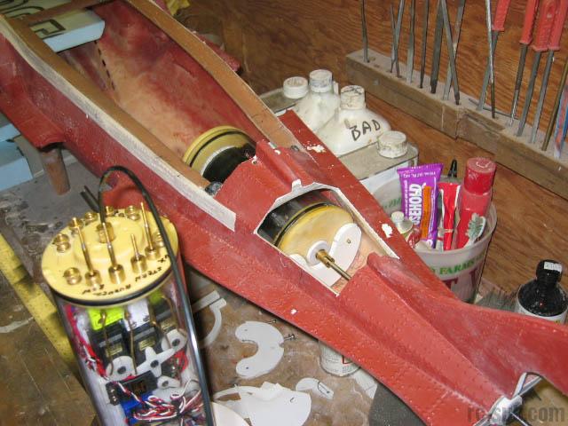
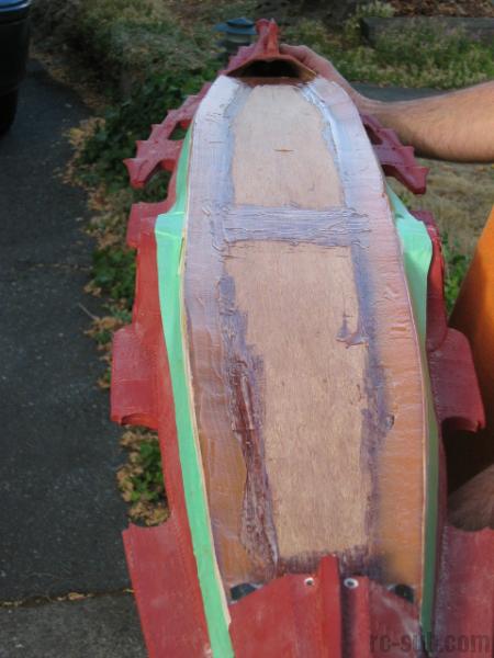
Alignment was becoming a large concern in terms of my access hatch. Greg Sharpe has come up with this great idea for maintaining the form of the hull and ensuring good alignment with the access hatch. This sheet of 1/8" plywood was epoxied into place and will have access ports cut into it to allow the installation and inspection of the components.
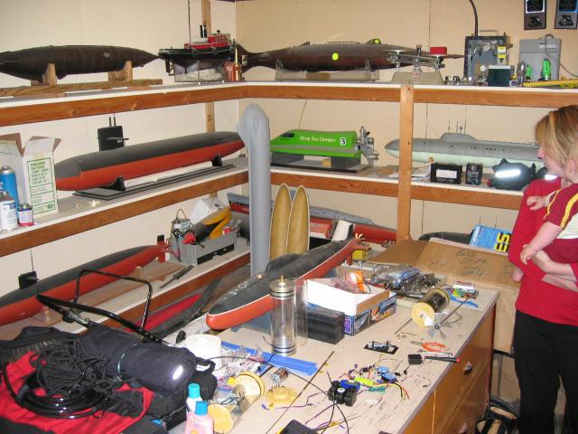
I also wanted to include this picture of Greg Sharpe's "lair". He's got a good number of RC subs, all of which are personally scratch built. He's built working torpedoes into one model.
Keep an eye out in the next few days for Greg's brand new website where he will offer his excruciatingly detailed blueprints of Russian and American nuclear submarines for sale. Also available will be his drawings for his own brand of Water Tight Cylinders and his one-of-a-kind waterproof transmitter case for snorkeling/scuba diving with your sub! Greg also has complete sets of plans for two separate Verne-styled Nautilus submarine models.
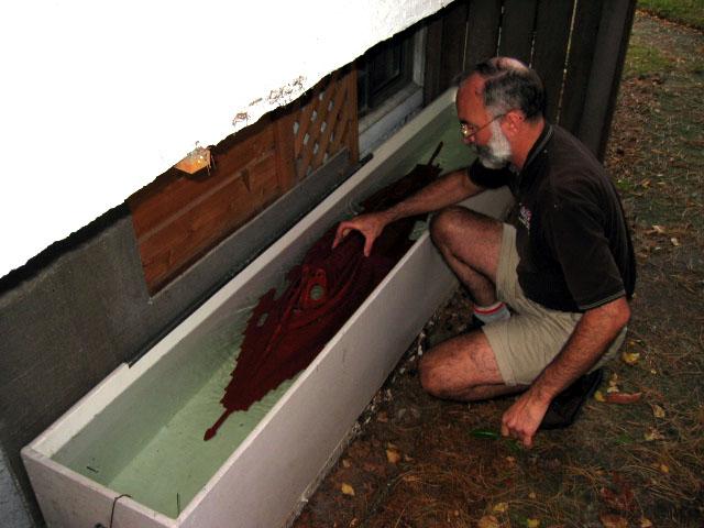
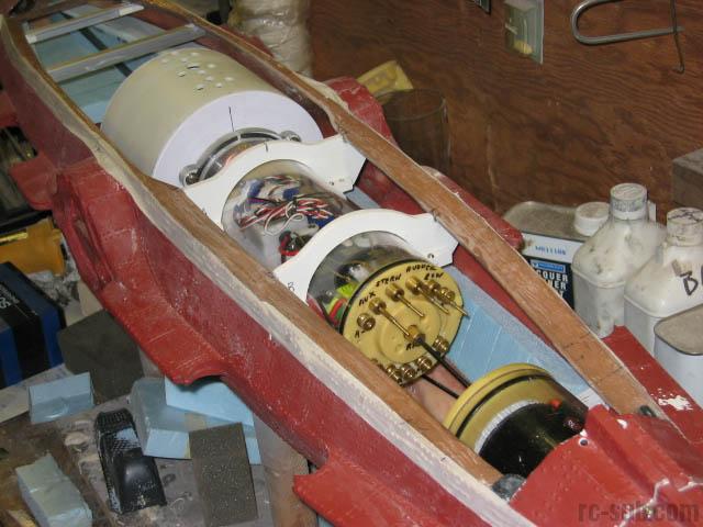
Here are some pics of water testing the hull with the motor compartment and battery mounts in place. Note the rear access hatch that will provide access for making up the rear drive shaft assembly. The man in the picture is none other than the intrepid Greg Sharpe himself, who has been helping me immensely in getting my model operational. This test tank is behind Greg's house and is used to test trim on his fleet of subs.

October 30, 2002
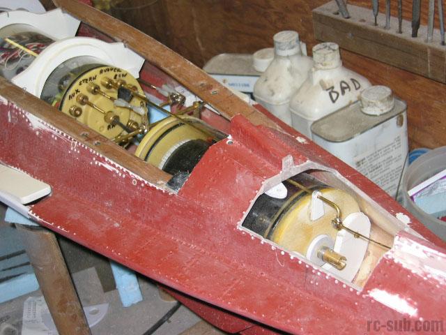
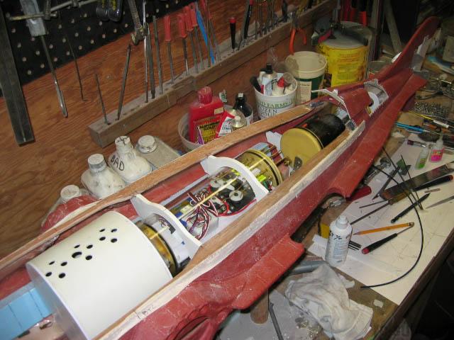
These shots illustrate the completed electronics WTC / ballast tank assembly mounted in the hull in front of the rear motor compartment. Blue foam has been added for buoyancy. You can see the aluminum battery rails in the forward section of the model.
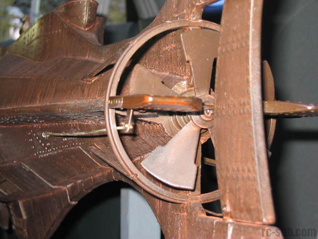
Greg also decided that my (rather amateurish) prop hub could stand reworking, so he fashioned a new one that's true to the original. I think I'll add a hobby lathe to my Christmas list!
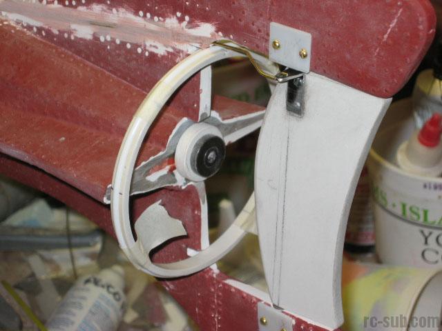
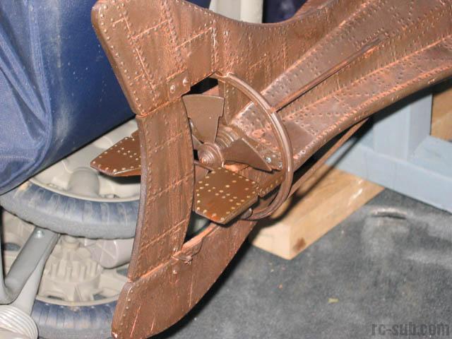
The rudder has been installed. Note the increased surface area nearly 30% greater than the original.
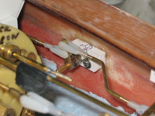
My prop ring has been fabricated, as is shown in these pictures. Control surfaces have been manufactured and linkages run, including a tricky rudder linkage install that Greg masterminded perfectly.
The forward and rear dive planes are run in tandem, working opposite from each other to maximize effect on the pitch of the boat. It will be easy for me to implement separate control through my depth keeper or APC if this arrangement does not work out, but Greg has a feeling that with the very small and inefficiently placed dive planes, this arrangement may be best. We will do wet testing to see if this holds true.
October 31, 2002
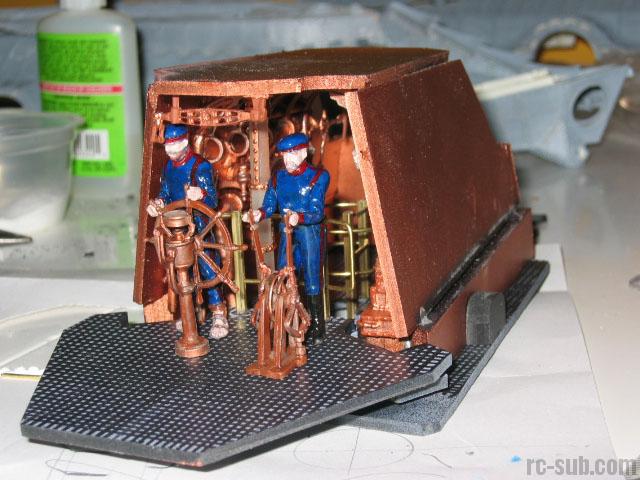
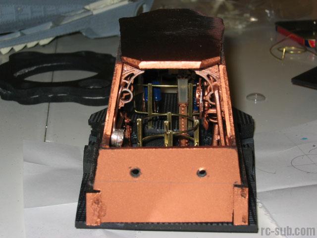
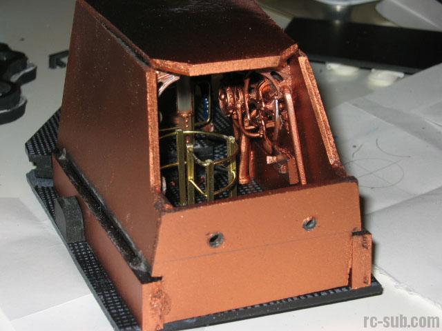
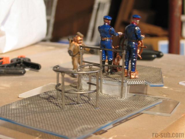
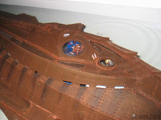
These pictures show my completed wheelhouse module. My crewmen have since been coated in a flat lacquer to get rid of the shine on their clothing. The wheelhouse sits in the conning tower recess and bolts into place with two fasteners. Detail pieces were obtained from Custom Replicas in California, and the brass railings were scratch-built.
October 23, 2003
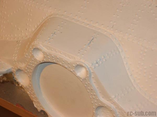
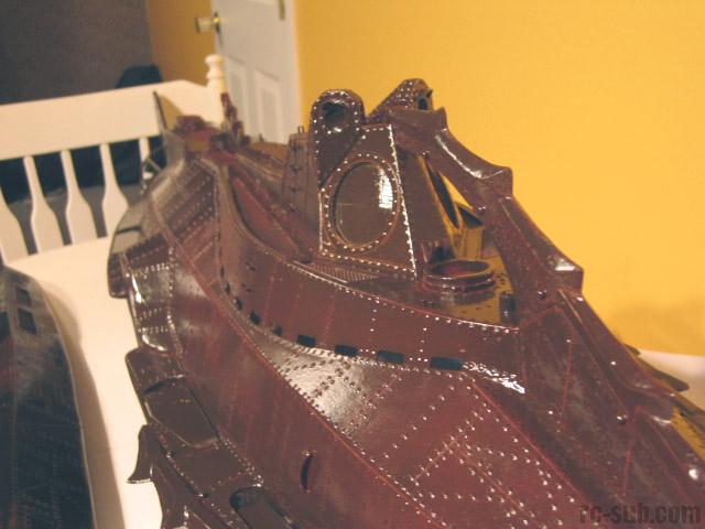
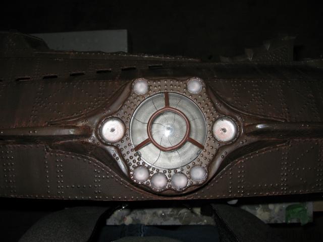
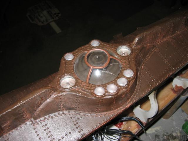
These shots were taken over the US Thanksgiving weekend (2003). As you can see, I decided to rework my salon window completely. The castings did not match up perfectly, and there was a 1/4" difference between top and bottom. It would have been mostly hidden by the salon window and floodlights, but it bothered me, so I ground off the bezel and manufactured a new one. Note the correct 8 panel iris. It turned out rather well, if I do say so myself.
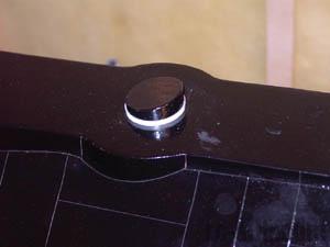
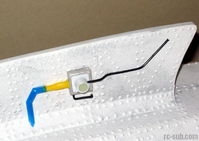
I also installed a waterproof switch for my main power. It is located just under the rear dorsal hatch, enclosed in a watertight case with a rubber boot for the switch arm..
The propeller shroud struts have been fabricated and installed as well. They were manufactured from 1/8" square brass tubing.
My wheelhouse and salon viewports were cut to size. They are made from a baby's toy (thanks to my son, LoJo), and cut to size with a Dremel cutoff wheel. They will be installed with clear silicone after the hull is primed.
Next steps are sanding the Bondo, cleaning the hull, priming with gloss brown paint, and redoing about 1,500 rivets (*sigh*).

October 24, 2003
Here are some shots of the work that has taken place over the last couple of days.
I've redone the details on the lower access hatch, as the drinking straws that I had initially used for the piping were making me nervous. I replaced them with brass tubing and I'm far happier with the product now. The wiring has also been replaced with brass.
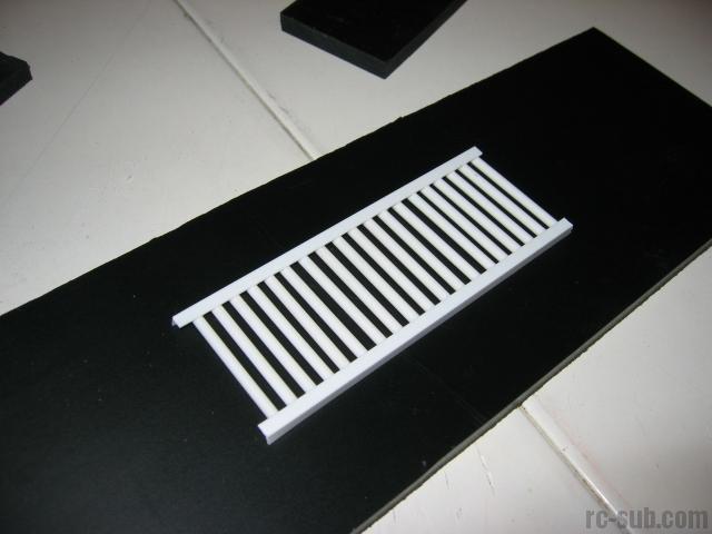
I've begun the finishing work on the ballast grating. I made up a jig to help with this process, as aligning 15 strips of styrene perfectly is challenging to do freehand.
The final pic in this series is a comparison of the Nautilus with my new 1:96 scale Russian Typhoon
October 25, 2003
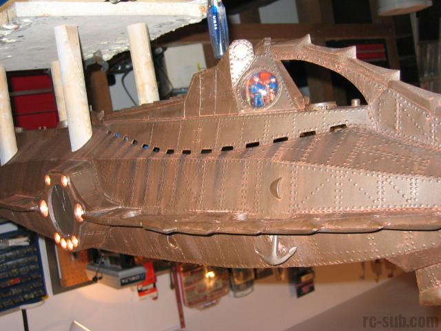
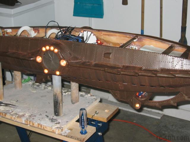
The model is now RTR (ready to rivet!). I've primed it with gloss brown spray paint, necessary to have the rivets bead properly. I estimate about 1000 or so need to be reworked. Detail pieces such as the water scoops, deck vent, anchor housing, alligator eye shrouds, and a few other misc. pieces have been added prior to painting.
These pictures are taken just after I finished painting and weathering the model. The process involved a lot of trial (but surprisingly little error). The base coat of gloss dark brown received two washes of diluted rust brown paint. When I say wash, I mean "wash". The diluted paint was literally running off the model, pooling in low areas and flowing between the detail pieces.
Satisfied with the result, I decided to spray on a protective coat of flat lacquer. Big mistake. The flat coat totally downplayed the thousands of rivets, and nearly obliterated the rusty wash. I was... upset.
I then decided to try another wash of rust paint. I'm glad I did. The flat finish took the paint well and lent a more reddish color to the model. Low areas and detail pieces still received a heavier pooling effect. All in all, I'm really happy with how it turned out.
I've already installed one of the two wheelhouse viewports and the lighting in all applicable spots since these shots were taken. I need to finish my three hatches, add my floodlight lenses, trim her out, and I should be done!


February 12, 2004
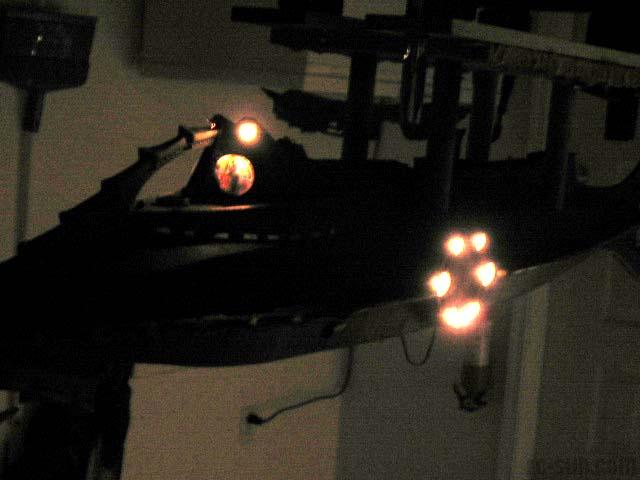
These shots show the lighting system installed and tested. The bulbs are 14V incandescent wired in parallel, 20 in all. They were secured to the floodlight recesses using clear silicone from the backside. The same clear silicone was used to secure the lenses to the outside. The floodlight lenses are composed of the clear plastic covers from "google eyes", and idea first brought to my attention when I got my SciFi Matters 1:72 Nautilus a few years ago. They work very well, as they are available in many sizes at virtually any craft store.
These shots show the (nearly) completed model, including installed salon portals, floodlight lenses, and even one of my completed hatches. Once the hatches are secured, I will be testing and trimming the model in my local boat pond, which I forsee happening this coming Sunday (Feb 15th), weather permitting.
February 14, 2004
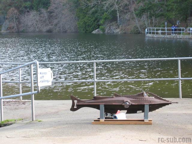
Testing Day! These preliminary trim tests were performed at the secret lair of Greg Sharpe, local sub guru. After the hasty construction of a secure stand, we proceeded with the first float test. The Propel Cylinder was charged and the sub lowered into the tank.
Lo and behold... the Nautilus sat high in the tank, but completely level! A quick vent and she proceeded to the bottom, slightly nose-first. This was very promising! We also decided to test out my motor and prop configuration. The moment of truth had arrived! We kicked the throttle in slowly and were very impressed with the response. At full throttle, the motor actually heeled the Nautilus over at a whopping 30 degree angle... now that's torque!
The model was taken back inside. Foam was redistributed and lead ballast added to the keel to help counteract the torque induced roll that we'd experienced. We dropped her back in the tank and tested her out again. She now sat dead level surfaced, and very slightly stern heavy submerged. This was barely noticeable, and we're going to leave it at that until after lake testing.
Total time spent trimming: four hours (including stand build-time).


February 22, 2004
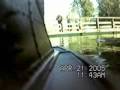
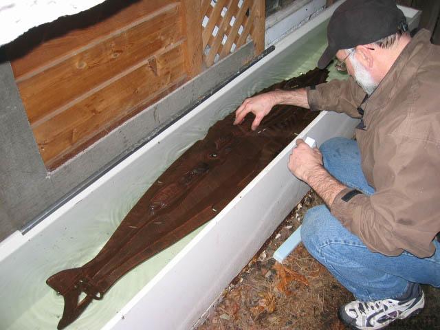
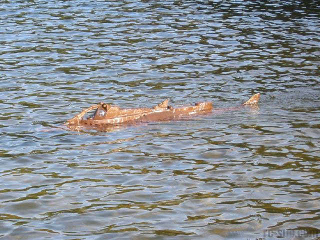
The Nautilus' maiden voyage was undertaken on February 22nd, 2004. Our chosen proving grounds were located at Thetis Lake, a location that offered a clean sandy bottom, crystal clear water, (and very few specatators so early in the morning).
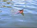
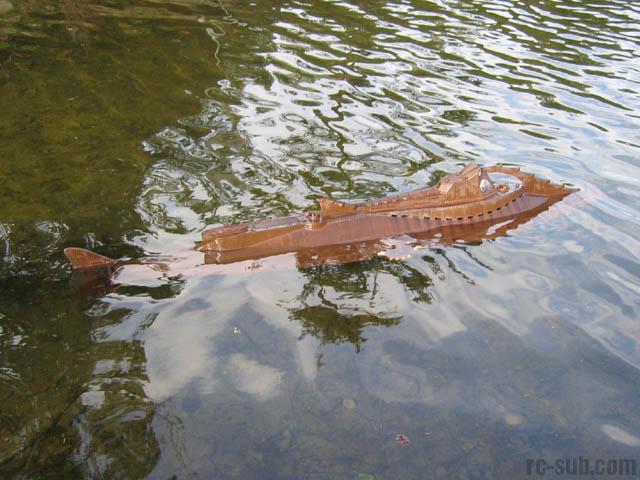
After properly securing the flotation foam at the workshop, we tested the model statically for submerging. Everything looked great. We then eased the Nautilus out of the slipway and took her for a short trip around the beach. The motor is extremely powerful, and tended to suck air at anything over 1/2 throttle. Venting the ballast tank slightly helped as the model dropped lower in the water. What we also discovered is that any amount of forward speed tended to push the nose of the model downwards, causing an unintentional dive.
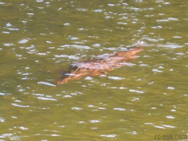
We pulled the model back out and checked the WTC's for leaks. None were found. By this time, my family had arrived and we performed a short dedication ceremony and officially launched the model. We undertook some submerging tests, which were slightly disappointing to me, as the Nautilus was difficult to dive without pulling the prop out of the water and losing forward momentum.
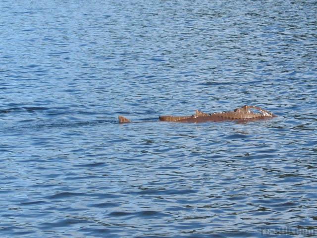
Greg and I decided to add some weight to the stern to see if it would help. Upon refloating the model, we discovered that the added weight did not significantly change her surfaced trim, but immensely helped her submerged handling characteristics. Additionally, her stock dive planes actually changed the model's pitch quite well.
All in all, it was an extremely successful maiden voyage. I will be adding this additional ballast permanently and retesting her at the Victoria Model Boat Pond this weekend (if not sooner). I'll also try to shoot some more video of her underway.

March 23, 2004
Thank goodness for minivans! My Nautilus fits just perfectly in the back and leaves just enough room for the baby stroller.
These shots show my newly added dive planes. The control for these planes is linked directly to the other four dive plane linkages. Together, they pitch the model quickly and efficiently. I intentionally mimicked the look of the rest of the model. Only true Nautilus purists should be able to tell that they don't belong. The planes still need to be weathered to perfectly match the rest of the model, but you get the general idea.

October 28, 2004
Here is a small collection of videos of my Nautilus in action!